Sunday, February 28, 2016

Fan-Tas-Tic Pinball, Part 3


Some impressions from the cleaning process

State of the playing field Before / After


I used white spirit and spot eraser pads for cleaning and automotive wax for sealing it.


The insides Before / After


The playfield has been stripped and all cables removed. I kept the leaf-switches but will read them in a matrix configuration.
It was possible to take out the relay based control board in one piece. The new ARM based control board is already in place.


In its original configuration, the pinball contains only one single transistor which is part of a delay circuit. All the other functions were done electromechanically.


Sunday, February 7, 2016

Fan-Tas-Tic Pinball, Part 2


The Fan-Tas-Tic controller

The new homebrew controller board for the pinball machine. It's general job is to read a lot of switches and drive a lot of solenoids. 

The game logic runs on a Raspberry pi, which communicates over a USB-serial connection with the controller board.


Mainboard, as rendered by KiCad


Mainboard, getting CNCed

Mainboard, tested and working
Unfortunately there was a glitch during toolpath generation of the second layer, which we only noticed very late in the milling process. While the board was functional, the high current traces for the solenoids turned out much more narrow than intended. They instantly burned up during the first test with a real solenoid (24 V, 3 Ohm, 8 Amps peak.). As a workaround I soldered thick copper wire on-top of these traces.

High current traces fixed


Driving WS2812 LED strings. Check of timing.


Saturday, February 6, 2016

Fan-Tas-Tic Pinball, Part 1


Refurbishing and upgrading a electromechanical pinball machine from the seventies.

      
Right: How it looks like now. Left: How it might end up


Taking the monster apart

Under the hood. This thing is full of relays and mechanical switches -- a lost art.
Underneath the playfield, showing the solenoids for the flippers.

At this point, the machine is in quite a bad state. All the rubbers have turned into brittle plastic, many lamps are blown, the playfield is a filthy mess and the playfield window is cracked.

We took a last video of the machine with its original electromechanical brain, before we have teared it completely apart:


Turns out it almost works. The score counting wheels have some issues. Sometimes they get stuck, sometimes the reset process never finishes.


Tuesday, November 11, 2014

Electric longboard

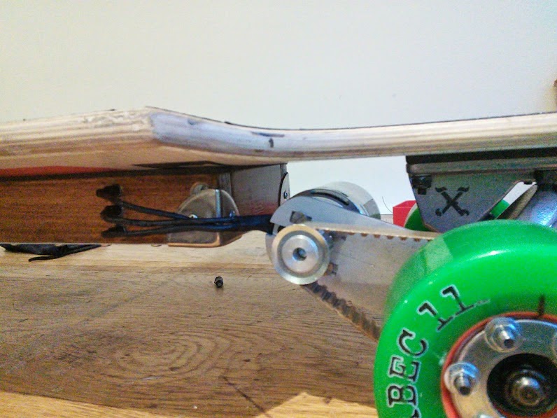
A large RC car brushless motor + huge Lipo batteries + a rather smooth to ride longboard = a lot of fun :)


Pictures and comments of the construction progress here:
http://imgur.com/a/aZsbh

The whole design is based on the experience from the endless-spheres forum:
http://endless-sphere.com/forums/viewtopic.php?f=35&t=53506


Tuesday, July 29, 2014

Fireflys in a jar

New! Webinterface

A toy webinterface for a similar jar can be found here:
Note that it is the real deal and the jar, standing next to my window, will actually start flashing if you click any of the buttons

 Ingredients

  • A large jam jar (Ikea)
  • Mini USB Nano V3.0 ATmega328 5V Microcontroller Board (eBay)
  • FTDI serial cable for flashing (eBay)
  • Solar cell, 5.5 V, 50 mA or larger (eBay)
  • Lipo - battery cell, 100 mAh - 600 mAh (eBay / old laptop / old cellphone, etc.)
  • 12 x tiny LEDs, different colors, the smaller the better, with ~80 - 200 Ohm series resistors, depending on how bright you want it (kit from eBay)
  • Very thin magnet wire from the coil of a miniature relais
  • SMD resistors with 1 % tolerance: 2 x 560 kOhm,  2 x 160 kOhm. For two voltage dividers to sample the solar cell and battery voltage
  • SMD ceramic capacitors, 2 x 100 nF, to stabilize the analog inputs of the AVR
  • Some circuit board, glue, prototyping wires, sticky tape 
The making-of after the click ...

Monday, March 17, 2014

The "Foculus Rift" part 3: Spoofing the EDID

The libOVR SDK recognizes if an Oculus Rift is attached to the PC by checking two particular things:
  1. The USB tracker with the right VendorID, ProductID must be present (this has been solved in Part 2)
  2. The Head Mounted Display (HMD) must be attached, which is nothing more than an ordinary monitor connected over HDMI. The HMD is identified by its so called Extended display identification data (EDID).

Tuesday, March 4, 2014

The "Foculus Rift" part 2: Reverse engineering the motion tracker

The function of the motion tracker is to estimate the current roll, pitch and yaw angles of the head mounted display (HMD), which allows the 3D game to know what you are looking at and render the scene accordingly.

The original Rift uses the following configuration (as nicely shown by ifixIt):
  • Invensense MPU-6000, gyroscope and accelerometer sensor
  • Honeywell HMC5983, magnetic field sensor / compass
  • ST  32F103C8, ARM 32 bit microcontroller (with USB connection)