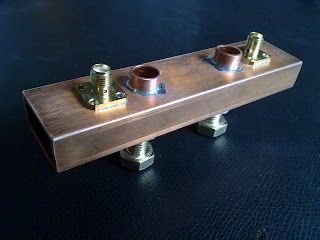
 For a recent project I needed a bandpass filter in the microwave range, made from non-magnetic materials. Remembering this very nice article from Paul Wade, I decided to give it a shot and roll my own. As the results turned out to be spectacular, I had to share this experience.
Mission order:
- center frequency = 1.74 GHz
- 3 dB bandwidth ~ 20 MHz
- As small and RF-tight as possible
- Quote from a company for this: 400 $ and 3 weeks lead time
For my first filter I wanted to start off with a design which was proven to work in that frequency range, so I just copied these parameters from Paul:
Filter 1
Distance connectors <--> capacitors: 12 mm
Distance capacitor <--> capacitor: 28 mm
The capacitors are 2 x M8 brass screws centred (with a small air gap) within two copper tubes. I cut 2 threads in the bottom wall of the waveguide to support the screws, the tubes are soldered to matching holes in the the upper wall.
This filter worked great and was easily adjustable from 1 GHz to 3 GHz. The waveguide itself is used far below its cut-off frequency (6.6 GHz for WR-90), so there is no actual electromagnetic wave propagation taking place. Signals coupled in on one side would normally be attenuated exponentially with waveguide length and only able to travel a few millimeters. Signal propagation is made possible by adding the two capacitors. They form a resonating circuit with the lengths of waveguide before and after each one. Signals on the resonant frequency can propagate, this forms the passband of the filter and works rather well, I measured less than 1 dB insertion loss for both filters I built.
 |
| Measurement of the first filter, showing its overcoupled passband on a network analyzer. It was not possible to flatten out these two peaks by tuning the filter |
For the first filter, with the top dimensions, it was impossible to get a flat response. No matter how much I tuned the 2 resonators, there were always 2 bumps visible. The two resonators were overcoupled and influencing each other. The solution is to increase the length of waveguide between them to weaken the coupling.
Before constructing the second filter, I did some simulations in CST Microwave Studio. Eventually I got confident in the simulation results as I could reproduce the measured data of the first filter quite accurately.
 |
| H-field in the filter, excited within its passband |
In the simulation I then increased the distance between the 2 capacitors, giving me the perfectly flat passband I was aiming for.
Filter 2
Distance connectors <--> capacitors: 15 mm
Distance capacitor <--> capacitor: 38 mm
Then it was hammer time!
 | |||
| A piece of WR-90 waveguide with the golden dimensions for a 1.74 GHz filter marked on it |
 | |||
| The additional parts you need: 2x M8 screws, 2x SMA connectors and 2x 10 mm copper tubes |
 | ||
| Drilling the holes accurately is the hardest part. Go all the way through both sides with the smaller drill to keep them concentric. |
 |
| Et voila, check that there's a little airgap and no short circuit between tubes and screws and then it's tuning-time |
 |
| Get a network analyzer and start screwing around. The passband of this one is easily adjustable from 1 GHz to 3 GHz, perfectly flat and about 25 MHz wide. Bullseye! |
 |
| The RF-tight result! |
And here is the measured and simulated filter response in comparison. The agreement is fantastic!
Zoomed in on the passband:
So building microwave filters is much more straightforward than I expected it to be. Sometimes it's worth to get your hands dirty :)


This is my first time i visit here. I found so many entertaining stuff in your blog, especially its discussion. From the tons of comments on your articles, I guess I am not the only one having all the enjoyment here! Keep up the good work.
ReplyDelete